WMM based coupled mode theory: Adiabatic directional couplers
M. Hammer
MESA+ Research Institute, University of Twente
(2001-2005, adapted 11.2021)
This page lists a collection of WMM application files that address the problem of guided light propagation through a straight (port) waveguide that is evanescently (vertically or horizontally) coupled to a ring (cavity) waveguide segment. See Ref. [1] for more details about the coupler geometry, about the implemented algorithms, and for results of the computations for a specific set of parameters. Ref. [2] summarizes how the properties of the directional couplers are to be embedded in a ringresonator model.

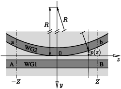
Top view of the directional coupler configuration: A segment of a cylindrical waveguide core (WG2) with radius R, evanescently coupled to a straight waveguide (WG1). Letters A, B, a, b denote the ports of the device, p(z) is the local y-displacement of the ring rim at position z.

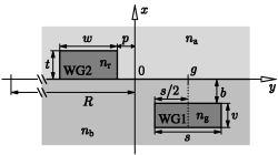
Coupler cross section: The port waveguide with core width s, thickness v, and refractive index ng is embedded in a medium with refractive index nb, buried at a distance b below the surface x=0 of that medium. The cavity strip of width w and thickness t with refractive index nr is placed on top of the surface, covered by a material with refractive index na. The horizontal position of the port waveguide is defined by the y-coordinate g (positive or negative values are to be considered) of the core center. p is the horizontal, z-dependent displacement of the ring rim.
Details about the WMM simulation framework can be found in the html manual, including instructions for download, compilation, and execution of the C++ sources provided. The application files are only meant as initial protoypes. The paragraphs on waveguide definition give guidelines how to adapt the programs to other cross section geometries.
|
|
Port waveguide, port.c:
Mode properties of an embedded channel waveguide with rectangular core. Program output: Propagation constants / effective mode indices ( stderr stream), mode definition files (.mod),
mode profile plots, horizontal and vertical mode
profile cross sections (MATLAB m-files).
|
|
|
Ring waveguide, ring.c:
Mode properties of a rectangular raised strip waveguide. Program output: Propagation constants / effective mode indices ( stderr stream), mode definition files (.mod),
mode profile plots, horizontal and vertical mode
profile cross sections (MATLAB m-files).
|
|
|
Ring waveguide, width dependence, ringdisp.c:
Propagation constants versus the width of a rectangular raised strip waveguide. Program output: Propagation constants ( ??pc??.xyf)
and effective mode indices
(??neff??.xyf)
in two-column ASCII files. First column: the core width, second column: the
propagation constant / effective mode index.
|
|
|
Coupler simulation, cpl.c:
Coupled mode theory analysis of the guided wave propagation along the composite coupler structure. Program output: Properties of the basis modes: Propagation constants and effective indices ( stderr), mode definition files (.mod, optional), mode profiles, translated to the
core positions at z=0 (MATLAB m-files).
Properties of the supermodes evaluated for
the composite refractive index profile at z=0: Propagation constants,
effective mode indices, coupling length (stderr), mode profiles (MATLAB m-files). The coupler scattering matrix with transfer
coefficient tau and coupling constant kappa (stderr).
Evolution of the amplitudes
C1 (port)
and
C2 (ring)
of the basis modes:
For excitation in port A
(C1(-Z) = 1, C2(-Z) = 0) the relative mode powers are stored in files
pAB.xyf (two-column ASCII files representing pairs z, |C1(z)|2),
pAb.xyf (|C2(z)|2), and
pAB+pAb.xyf (|C1(z)|2+|C2(z)|2).
For excitation in port a
(C1(-Z) = 0, C2(-Z) = 1) the relative mode powers are stored in files
paB.xyf (|C1(z)|2),
pab.xyf (|C2(z)|2), and
paB+pab.xyf (|C1(z)|2+|C2(z)|2).
|
|
|
Coupler simulation, parameter dependences, cplsc.c:
CMT analysis of the coupler structure, scattering matrices versus the relative core position. Program output: Basis mode properties: Propagation constants and effective indices ( stderr),
mode definition files (.mod, optional). Transfer coefficients
tau and coupling coefficients
kappa
in two-column ASCII files. First column:
the geometrical parameter (the burying depth b in the original
program file), second column:
|tau|2
(tau.xyf),
|kappa|2
(kappa.xyf),
and
|tau|2+|kappa|2
(total.xyf).
|
Approximations and assumptions
Some of the approximations and assumptions the coupled mode approach is based on are mentioned in Ref. [1]. Additionally, the recipes that were originally derived and implemented for composite, longitudinally invariant structures (see Ref. [3] for details) are here applied to a device with z-dependent refractive index profile. Reasonable results can thus be expected only for an intermediate range of core distances (more precise: observations in [3]) and for relatively large ring radii (do not forget to adjust Z accordingly). The specific form of the couplers allows in a certain respect to check the consistency of the simulations:
-
According to the model assumptions, the device should be power conservative.
Consequently, the files
pAB+pAb.xyfandpaB+pab.xyfas produced bycpl.cshould contain only unity values in the second column The same should hold for the sum of the scattering coefficients in the filetotal.xyfrelated tocplsc.c. -
By virtue of the symmetry with respect to z=0, the complex valued
coupler scattering matrices
Tin the output streams ofcpl.candcplsc.cought to be symmetric.
Necessarily the simulations satisfy these conditions only approximately. One should not trust the results to a degree that is higher than the accuracy observed in the above relations.
Strictly speaking, the "power coupling" matrix should appear in the expressions that evaluate the modal power. This becomes relevant for local configurations with "strong coupling", with pronounced mode overlaps. Hence, in particular for intermediate positions (z around 0), the interpretation of the squares of the individual amplitudes of the basis modes |Cj(z)|2 (and of their sum) is not straightforward. Nevertheless, assuming "decoupled" waveguides at z=-Z and at z=Z, the interpretation of the squared amplitudes as guided output powers is adequate.
For specific configurations, the relations may be pronouncedly violated, as a consequence of the approximations inherent in the present CMT version. However, in these cases we have observed the deviations bewtween the two offdiagonal elements of the coupler scattering matrix to be of the same order of magnitude as the violation of power conservation, where the average of the two coupling coefficients fits relatively well to the - almost coinciding - transmission coefficients, the diagonal elements of the scatter matrix. The programs cpl.c and cplsc.c therefore declare the average of the offdiagonal elements as the approximation of the coupling coefficient. Particular caution is advisable when using these results.
Technical remarks
- While the coupled mode theory procedures are comparably robust, the mode finding algorithms are not. This is to some degree inherent in the physical problem itself, at least if it comes to the question whether or not a given refractive index profile supports a mode of a specific polarization or order. Confer the remarks on the mode analysis procedures and the mode solver parameters, if corresponding trouble is encountered.
-
The programs write simulation results (if few data values are concerned) and
log-information to the
stderroutput stream. In contrast tostdout, thestderraccess is unbuffered, hence the data is more likely to survive an unintended end of the program execution. The sections about filenames and the log information comment about the types of output produced by the WMM programs. -
For diagnosis purposes, each time the mode solver is invoked it writes
a file named
???sev??.xyf(with the?s replaced by characters that identify the simulation type) that records the evaluations of the least-squares error function the WMM approach relies upon. In particular for the dispersion calculation many of these files appear; delete these after a successful completion of the programs. -
Success of the input and output operations is not controlled
internally. Hence before starting a program with the statement
CalcBasisModes 0, it should be made sure that the relevant mode definition files are present in the directory where the program is executed.
Microresonator simulations
Relying completely on the properties of straight waveguides, these programs have to be complemented by results from a suitable bend mode solver when aiming at a 3D model for the microring-resonators that are investigated in the NAIS project. This concerns the mode attenuation in the curved cavity waveguides in the first place. In a second place, available bend mode properties can prospectively help to improve a coupler design found by means of the WMM CMT programs: Given the mode profile and propagation constant of the straight basis field for the ring core, one could try to modify the core geometry and position, such that the bend mode calculated for the new core with the appropriate radius coincides as far as possible with the original straight field. This concerns the position of the field maximum, adjustable by a slight shift of the relative core positions, and the effective mode index, which can be matched e.g. by a change in the cavity core width.
References
[1]
Coupled mode model for 3D directional couplers,
NAIS internal note, September 2002.
[2]
Standard ringresonator model,
NAIS internal note, April 2003.
[3]
M. Lohmeyer, N. Bahlmann, O. Zhuromskyy, and P. Hertel.
Radiatively coupled waveguide polarization splitter simulated by
wave-matching based coupled mode theory.
Optical and Quantum Electronics 31, 877-891 (1999).